Monday, November 5, 2012

Review: O-Scale (2R) - Mike's Train House (MTH) - SOU F7 ABA

I received my set of Southern Railway F7's a few weeks ago and while there is a lot of work to do to make them right, they are a great base model and I felt they were worth a basic review.  I think John Sethian is working a really detailed review in OST, so I didn't bother asking Joe to review these.  There are also some cool things John will be doing to upgrade his and I will be too, but outside adding the new-style Kadees, I haven't modified mine.  So here we go with my photo essay (captions underneath each CLICKABLE high-res photo)


What the box reads on the outside...


Paperwork that is inside the box on top of the styrofoam.  The quick guide on the left is bare bones and tells the DCC operator to go look up the product online and find the DCC guide.  As of now, 20-20191-2 still doesn't have a detailed instruction manual and I never received a response from MTH on why.  Instead, I had to go view the HO instruction manual and the DCC section there appears to mirror exactly the HO version as far as I can tell.  You will need that to get the listing of the CVs, etc, but as a favor you reading this, I took a screenshot of the 29 functions and list it below:


So you never bought an MTH F or E ABA set huh...well this is what they look like brand new from the factory.  Now try to wrap them back exactly like that each time you put them away...


On my unfinished small switching layout, here is a look of the slave A unit with the kadees installed.

Side profile shot with that newly tooled blomberg truck.  Pretty nice.  I just wish they made it easy to change out the bearings used on their trucks and sold those as a separate detail pack as these trucks only have roller bearing on all 8 spots.  Often many roads had mixed bearings on their units...


A close up of the pilot detail.  They shrunk the hole for the kadee.  Less huge gap for it.  I like it.  The screws for the kadees didn't come in the box like past 2R MTH diesels.  I had to tap the holes for 2-56 screws. Obviously a freight pilot.

A closeup of the newly tooled blomberg trucks.  Feel free to rivet count to your hearts content.  Look good to me other than being stuck with the roller bearing sections.


An angle nose shot.  I like how they added these service grabs, but these particular units never had them from what my references show.  The font of the numberboard is also wrong.


The exhaust vent on both units came with the paint scraped off.  Very odd...


So this is probably MTH's only 5-chime horn that comes close to an M5.  The M5's were popular on many roads, so I am confused why they never made the casting.  It must be replaced on both A units.


Here is the end of the slaved A unit.  Rubber diaphragm/door along with rubber MU hoses.  Not very realistic but I understand the desire for rubber airhoses.  I will have to replace, along with putting the tether through the door.


The door on both A units open for the controls.  Shown is the slave unit.  Not much to select, but plenty of openings to get the tether through (or enlarge the openings...either way...


Here's what the main powered A unit has.  Still room to get the tether through, but the current settings show that it is set for 2R DCC with the option to go to 3R (pickup rollers in box) or to DCS.  I keep the smoke turned off, but these do supposedly smoke.  I have no interest until after I do all the detail work.  The sound POT does not work in DCC.  Instead it is controlled by using the F6 key and can change it up 10 levels or so.


The lead A unit has this nasty creature for the tether along with the non-functional kadee and rubber air hoses.


Here's what the truck blocks look like.  Can easily screw in the 3R pickup roller.  Look at the huge space between the 2R wheels and the frame.  Supposedly easily fixable by John Sethian.  I will await his detailed article at some point to proceed.


Added my Kadees with 2-56 screws.  Tapping required I believe, but taking off the pilots was not.


Here's what the only speaker in this trio looks like.  Comes with PS3 freight sounds and inspected by #1?  Will look to expanding sound to the B and slave A unit.


Close-Up of non-function kadee between units.


A glimpse at the wiring mess of the tether...


Proof that these close couple as-is, but the tether is hideous.  It will be completely hidden by the diaphragms once I get around to moving them.  Wish MTH thought to move them first.

Now that the model is shown in detail, here is info on the prototypes MTH chose:
  • Southern had 76 F7A units.  Most were originally SOU with 9 from the CNO&TP and AGS.
  • Southern had 72 F7B units.  Most were originally SOU with 27 from both CNO&TP and AGS.
  • These were all equipped with 567B engines.
  • 4242 was built in 5/49 with Dynamic brakes installed in 23Oct53 at Spencer, NC shops..  Retired in 1969.
  • 4228 was built in 6/49 with Dynamic brakes installed in 25May55 at Spencer, NC shops.  Retired in 1973.
  • 4400 was built in 5/49 with Dynamic brakes installed in 22Apr53 at Spencer, NC shops.  Retired in 1969.

Using photos from both my physical and digital library...it would appear the following needs to happen to bring these closer to the prototype for my time frame(though all photos I have are only within my time frame, so I'm curious how MTH screwed up the service grabs...)
  • Remove the service steps on both A units.  They were not installed on these 2 particular units.  
  • Add the obviously missing MU and air hoses to the pilots.
  • Add roof coils and spark arrestors to both 4242 and 4400.
  • Replace the horns with brass Nathan M5 castings
  • Add speed recorder and ATS shoes to appropriate trucks.
  • Re-tether the ABA units through the diaphragm instead of through the truck.  
  • Redo MU hoses on rear of both A units and on both ends of B unit if feasible - Installed rubber ones may be required due to 36" radius curves
  • Maybe try to add sound to the B and other A unit if feasible.
  • Numberboard Font is off.  Need to check Microscale decals to see if replacing is feasible.
  • Potentially body mount kadees if feasible
  • Potentially body mount side truck steps to frame if feasible
  • Move the truck sideframes in if admittedly...John Sethian's way of doing it turns out to be easy.
  • Get inside the nose lights/cab and paint the LEDs with orange translucent paint to make the bright white turn more warm white.
  • Weather to 1968 conditions
End of my review.  You're bound to see my changes when they eventually occur as I finish them.  So many other projects I am more motivated to complete first.

Here is a video of my units to show a few of the functions easily achievable with my Digitrax DT402D.  The video shows flickering of the lights, but it is entirely based on the camera's shutter speed seeing faster than our human eyes can and I can't easily fix it.


My final thought is that I wish MTH made some of these F7A units as dummy 2R units.  Would be nice to run these elephant style as in the prototype.

Tuesday, October 23, 2012

Iwata - Amazing Customer Service

I just have to share this good deed (or amazing customer service...).

I bought an Iwata Smart-Jet compressor for my Paasche Airbrush.  I bought it for several reasons at the time as it is a known quality name-brand, had positive reviews at the time, can hold my airbrush, included a moisture trap, and it knows when to turn the air on/off all on its own.  This last option is nice, so you don't have to keep flipping a switch, or fill up a tank every so often.

So after several years of use...probably 4 or maybe even 5, my compressor stops working.  I can't figure out why, but I figure trying to get it fixed would be cheaper than buying a new one as its still in good shape.  I called tech support and the gentleman gave me a few ideas for the model I was using, but told me that it was probably the pressure switch and they no longer use the part I have on mine.  The back up plan that where I could not figure out what was happening or fix it, was to mail back the compressor with $50 and they would fix it with return shipping included.  Even that isn't a bad deal for a quarter of the price of it new.
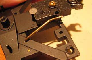
I took the advice first and I hit the pressure switch with a hammer and it would turn on sporadically every time I did that.  It was a sign that the switch was broken. I ended up taking it off and opening up the part.  A broken copper connector that is used to push a pole into the air-flow gap had broken, probably from lots of use.

In an attempt to get just that part to fix the switch, I emailed the photo to Iwata and a customer service rep actually replied and said they would send me an entire pressure switch free of charge; no worries that the compressor was way past the one-year warranty mark.  I never had to send it back and the part usually runs $20 by itself.  Now that is service.  I will stay with their products if I ever need to actually buy a new one.
Here is a link to the compressor itself... http://www.iwata-medea.com/index.php/products/smart_jet


Broken Switch (copper part inside)


New pressure switch wired in and screwed in.

Thursday, September 6, 2012

My Layout: Wiring AtlasO Turnouts Part 2

So I am very close to having all of the turnouts I need to complete my switching layout.

With that, I've already started laying most of the track and before I could finish that step, I wanted to go ahead and wire the turnouts to avoid failure and frustration later, due to failure of AtlasO switches (the contacts under the switches fail over time)

Cutting away parts of the plastic substructure under the rail is easy as is soldering to that (as witnessed in Part 1), but the frogs gave me some trouble and are shown below. I was using my Weller 50W variable soldering iron set at 850 degrees and even after filing a section of one of my wyes, I was not able to heat sink it enough to keep the frog from melting off the ties.  The alloy they use also corroded.  I did not have silver solder at the time to try to solder to this, so I went ahead with the method below.  Silver solder may work, but I have not experimented with it at this time.


After some suggestions from the OGR Forum, I decided to go ahead and potentially make eyesores on all of my frogs by drilling a hole in them and tapping them for .25" 2-56 brass screws so I could solder to the heads from the bottom.  I will be wiring all of the frogs to some Tam Valley Frog Juicers. 

Another tip was to add styrene spacers to the frogs to ensure they don't short with any of the other rails from either movement or rail expansion.


Below is one last photo.  It shows the top and bottom of how the rails are connected and where I chose to cut the ties to add my own wires.  The top photo shows the frog in red - it is isolated from the rest of the switch.  The blue and green lines show the same rails that should be connected and where I wired across under the rail.  On one side of the turnout, I soldered pigtails that would all three go together through a hole under the layout to connect to the 10AWG bus I have running around the layout.  Those pigtails and small hole are drilled after I lay the roadbed, so that they are really close to the roadbed and will eventually be entirely covered and hidden by ballast.


Hopefully this provides a stepping stone for others to use to do similar work to do their best to hide wires on the rails.

Thursday, May 10, 2012

Modeling: Magnetic Air Hoses Part 4

This post shows how I did the magnetic air hoses for an AtlasO 50' Plug Door Boxcar that the prototype had extended cushion couplers.

The coupler boxes are made by a guy of the last name of Gougen.  They are made for the Kadee couplers to be inserted, but attach to an AtlasO boxcar using the different screw spacing unique to Atlas cars.

I looked at a prototype picture and basically the pipe extends back into the car, so I bent the wire at 90 degrees far enough back to be away from sight, but to extend through the box twice so it has a second hole that won't allow it to turn vertically.  I trimmed the brass wire (see part 1 for exact sizes of bits and wires) so that it would barely stick out of the second hole on the other side of the box.  The other end was trimmed to keep the angle cock flush with the end of the coupler box.  The photos showed the end of the pipe coming to the angle cock to be bent down, but it would put the glad hand too low and be down in the height of the ties.


Tuesday, May 8, 2012

My First AtlasO Turnout Wiring Attempt

I was looking for ideas on what needed to be addressed and how to address shortcomings of AtlasO's 2R turnouts...here-forth called switches.

I was told to not trust the copper cross plates on the underbelly of the switches and to add my own wires to the frog, both sets of rails and also possibly the points, but I decide to let the points use the built in copper plating in the ties.

I went ahead and soldered 5 wires; one to the frog, one to each the right and left rail on one of the diverging ends, and soldered jumpers to the other diverging end's rails to assist the embedded copper plates.  I wanted to see if I could do the soldering myself without a resistance soldering machine, and I wanted to see if I could solder to the bottom to the rails to avoid unsightly solder joints on the side of rails.

It was suggested on the OGR Forum to use wet paper towels to  act as heat sink for a soldering iron.  I went a step further and soaked a sponge in water to do the same.  I set my variable setting soldering iron to its highest setting-850 degrees or so.  I used solid 18 gauge wire for all connections.

To prepare for the connections, I cut away several pieces of ties (see photos) in such a fashion that it would not hurt the overall integrity of the one-piece plastic tie casting. (I choose pieces between the ties that were at diagonals and/or were opposite of sections that weren't cut).

At this point, I filed all areas I was going to try to solder to.  I then added flux paste to each area.  I then tinned both the wires and the rails.  Tinning the rails was easy.  The frog is a big metal casting, so it took a lot of heat to tin it and you could hear the sponge sizzling from the heat.   I did push the switch into the sponge to ensure good contact with water and I did make sure not to melt any of the ties.  I was able to easily solder the wires to the rails by bending the ends of the wire into an L shape to allow more area to solder to the rail.  I did the leads first and then the jumpers.  An idea for the future would be to cut a piece long enough to do the jumpers and the leads and just strip some wire also in the center of that one wire so it can all be one piece and I wouldn't need to worry about the lead coming off when I try to solder the jumper.  The frog was a pain and as I tugged hard on the lead to make sure it was a good solder joint, it pulled off easily twice.  After each time I filed the same spot again and even harder than the time before.  I put more flux paste each time and got the third time to hold pretty strong.

I am curious to see how a resistance soldering device would make this any easier or stronger solder joints.  Perhaps I should consider using a high grade silver solder.  If anyone knows of a good resistance soldering unit for sale, let me know.

Here are some photos.  Feel free to click on the photos for larger sizes and to comment as always.


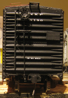
CN and NKP finished kits

I had the pleasure of building 2 kits for a friend of mine.  Sad to say, I hope they are the last 2 I ever build for anyone outside selling anything from my personal collection.  It just takes too long too build kits at a higher quality level.  I do want to say that the Sylvan car did have an older set of decals that were falling apart in the water and were scratched off.  Sylvan amazingly replaced these at no cost to me and it was appreciated.

The two kits are the following:
-Sylvan Models CNR 1929 Boxcar
-Chooch NKP War Emergency Boxcar

The Sylvan is a two-piece body kit and comes with everything but trucks and couplers.  The ladders are a bit crude, so I opted to use a modified plastic set sold by Des Plaines Hobbies.  The CNR decals appeared to be missing a lot of little extras that I saw on some photos of cars in the 50s.

The NKP kit was a flat kit and needed its entire body squared up and put together.  It did not come with trucks, couplers, decals, or a roofwalk. I ended up getting one of the last sets of decals from Nickel Plate Models (Dave Vaughn), but he said he could get more printed if needed.  The etched apex roofwalk I used was also from Des Plaines Hobbies.  This makes for a superior model in the end. 

The cars are fitted with Weaver trucks (with some washers in between the bolster pieces due to clearances needed from the flanges and bottom of the car.  The cars still meet kadee heights)
The CNR car got boxcar red.  The NKP car got mineral red and black.  The trucks were painted for NKP car per the photo I saw and the only weathering any car got was with the oily black on the inside of the wheels of the NKP trucks.

Can't think of much else to say, so here are some photos of the end results:


Magnetic Air Hoses Part 3

This post is for the AtlasO Fishbelly Hopper.  This one was a bear of a job to do, but luckily the bolsters come off the hopper.  They are diecast, so it is a bit more work to get things to work.

For the kadee couplers, I redrilled and retapped the holes for 2-56 screws.  I then used 1" screws at angles to screw down the coupler and trimmed the tops to make them flush.  Everything gets touched with black paint to blend it all in at the end.

For the A end of the car, I was able to drill into the side of the piece that the coupler screws into using a #55 bit.  I had to be careful drilling to widen it slightly to take the brass wire that I bent to get the air hose at the correct height and angle.  I filed down both ends of the wire and went to solder the angle cock casting to one end.

For the B end, the notch that holds the triple valve kept me from drilling into the side.  I thought to drill at another spot, but I instead was able to use the 2 holes that originally held the AB Reservoir and bend them in place to hold the angle cock.  I was able to bend a piece first try to fit in both holes and soldered the angle cock onto the correct end.  For the AB Reservoir, I cut off the two pegs and made sure the "wires" into the A and B sides from the triple valve were glued so that the triple valve could hold the AB Reservoir in place.

The rest was simply putting together the glad hand, painting, and screwing the bolster pieces and trucks back on.  See photos below for some ideas...